
Load case 1
Vertical loading of the main rollbar
 Figure 1 shows the finite element mesh based on quadrilateral shell elements. The stamp is positioned right over the highest point of the original main rollbar covering the entire width of the cage. The load is then applied in negative vertical direction. The Thiebaut structure is fixed at eight mounting points. The load F1 is calculated according to the following formula :
F1 = 7,5 x (1.280 kg + 150 kg) x 9,81 m/s² = 105.212 N
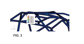
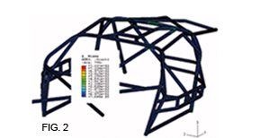 Figure 2 shows the distribution of v. Mises equivalent stresses. Minor plastic deformations take place at areas of stamp contact and related plastic strain values locally reach about 7% of plastic strain (figure 3).
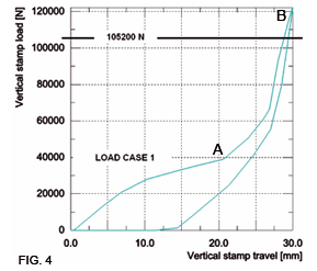 The load displacement curve (figure 4) shows two distinctive slopes on the loading path. Up to point A, the loading curve is rather flat, indicating a low stiffness. This is related to the bending of the middle section. Hereby the stamp is not yet in contact with the vertical parts of the main rollbar. Therefore the stiffness in this section is rather low.
From point A to point B, the roll cage structure shows its actual maximum stiffness. The structure is loaded up to 121 000 N which corresponds to over 115% of the maximum required load of 105 200 N.
The displacement at 105 200 N reaches 27 mm and remains at 14 mm after unloading.

F1 = 7,5 x (1.280 kg + 150 kg) x 9,81 m/s² = 105.212 N


From point A to point B, the roll cage structure shows its actual maximum stiffness. The structure is loaded up to 121 000 N which corresponds to over 115% of the maximum required load of 105 200 N.
The displacement at 105 200 N reaches 27 mm and remains at 14 mm after unloading.
